

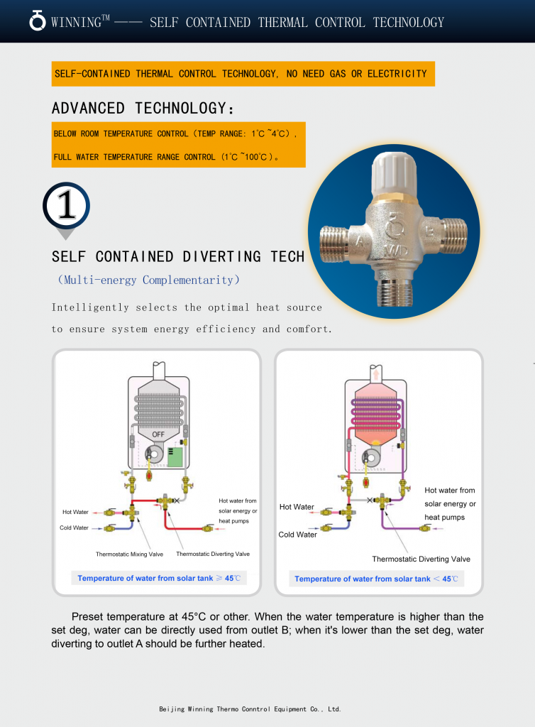
Residential Instant Water (Zero-Cold-Water) Upgrade Solution
During installation, ensure that all dust and foreign particles are thoroughly removed from the unit and its connected piping. Install the directional control valve at the cold water inlet of the point-of-use electric water heater (commonly known as a “mini water heater” or “under-sink water heater”). When the hot water tap is opened, the mini water heater immediately supplies hot water, simultaneously flushing out and utilizing the cold water remaining in the hot water pipe.
This instant water upgrade solution integrates the functions of a check valve and a thermostatic valve into a single component. It eliminates the need to wait for hot water circulation and removes the requirement for traditional instant water systems to install a dedicated recirculation pump, separate thermostatic valves, or check valves to isolate the hot and cold water lines. As a result, it significantly reduces both initial installation costs and complexity, while cutting overall system operating costs by more than 30%.
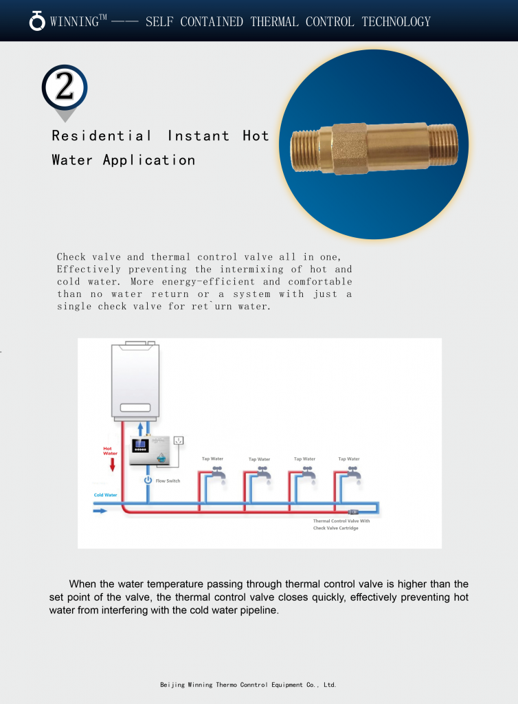
Residential Zero-Cold-Water Hot Water Applications
This system effectively prevents cross-mixing between hot and cold water lines, offering superior energy efficiency and user comfort compared to conventional return-water systems that rely solely on a check valve.
When the water temperature passing through the zero-cold-water thermostatic valve exceeds the preset threshold, the valve rapidly closes, thereby preventing hot water from migrating into the cold water piping. The thermostatic valve is factory-set to activate at 37°C (or another specified temperature) and can be customized to meet specific customer requirements.
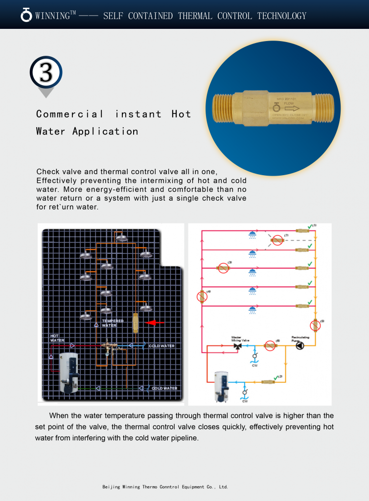
Commercial Zero-Cold-Water Hot Water Applications
This system reduces initial investment and operating costs while ensuring consistent, thermostatically controlled hot water delivery—providing truly instant hot water at the point of use.
When the water temperature in the system falls below the setpoint of the thermostatic valve, the valve automatically increases flow rate to rapidly raise the pipe temperature to the desired setpoint. Conversely, when the water temperature exceeds this setpoint, the valve automatically reduces the flow rate, allowing the temperature to quickly return to the target level. This dynamic regulation establishes a continuous balance between heat loss and thermal replenishment, achieving instant hot water availability while minimizing energy waste to the greatest extent possible.
What precautions are needed when installing a freeze-protection valve?
1. Always remove dust and foreign particles from the valve and connected piping before installation.
2. Ensure that the horizontal pipe extending from the valve has an upward slope of at least 1:100.
3. When installing in an inspection chamber, provide a minimum 200 mm drainage clearance beneath the valve outlet. This space may be filled with a dedicated drainage mesh or gravel to facilitate water infiltration.
4. Handle with care. Do not expose the valve to excessive heat or direct sunlight, and never install it in non-potable water systems.
5. Install the valve in accordance with the flow direction indicated by the arrow marked on the valve body.
6. The valve must be installed below the local frost line. If installed above ground, ensure that all piping upstream of the valve is protected from freezing; no insulation is required downstream of the valve.
7. In anticipation of freezing temperatures, fully rotate the valve handle in the direction of the drainage arrow to completely drain the water. Additionally, open all faucets within the protected zone to fully drain the system, then close them. Whether for normal use or freeze protection, always turn the handwheel fully to the open or closed position—never leave it partially turned.
8. It is recommended to install a backflow/odor-prevention drain valve (anti-siphon or anti-odor valve) at the drainage outlet to prevent sewage or odors from backing up into the piping system.
9. It is recommended to install a main isolation valve upstream of the freeze-protection valve to facilitate maintenance, servicing, or replacement of components.
In freeze protection applications for heat pump water systems, the freeze-protection valve is capable of autonomously assessing the system’s operational status. In the event of unexpected shutdowns or power failures, the valve automatically activates its freeze-protection mode. When the sensed temperature approaches freezing point, the valve initiates a “trickle-drain”strategy—releasing small amounts of water to prevent freezing.
As the discharged water temperature decreases, the valve dynamically increases its drainage flow rate to effectively compensate for heat loss within the system. Conversely, as the water temperature rises, the valve progressively reduces the drainage volume until it fully closes.
This intelligent, temperature-responsive mechanism ensures reliable freeze protection while minimizing water consumption—making it an energy-efficient and environmentally sustainable freeze-protection solution.
1.Opening/Closing Temperature
Typically, an activation temperature range of “1-4°C” is used for pipe freeze protection, while “3-6°C” is recommended for solar thermal collector freeze protection. These ranges(1-4°C and 3-6°C)represent the optimal balance achieved by our R&D team through extensive testing across key performance indicators, including freeze protection effectiveness, energy efficiency, and water conservation.
For example:
– A wider range such as “3-8°C” would lead to unnecessary water discharge and waste.
– A lower range like “0-3°C” compromises freeze protection reliability.
Therefore, the “opening/closing temperature” is a critical parameter for evaluating the performance of a freeze-protection valve during selection and testing.
2.Maximum Operating Temperature
The “maximum operating temperature” refers to the valve’s ability to withstand high temperatures. It is essential to ensure that the freeze-protection valve is never operated beyond this limit.
While many assume that freeze-protection valves only need to function in cold conditions and thus do not require high-temperature resistance, this is a misconception. In practice, these valves are often connected to heating or hot water systems where fluid temperatures can approach “100°C”. If a valve is rated for only “60°C or 70°C”, its service life and freeze-protection performance will be significantly compromised.
We strongly recommend that “high-temperature resistance be included as a key criterion” in product testing and evaluation.
3.Flow Coefficient (Kv/Cv)
The “flow coefficient” is a measure of the valve’s discharge capacity. When system water temperature approaches freezing, the freeze-protection valve must “rapidly and effectively drain cold water” to prevent freezing. Even with a valve installed, inadequate drainage can result in system freeze damage. Thus, the magnitude of the flow coefficient directly determines the valve’s freeze-protection capability.
Common Misconception: Some believe a higher flow coefficient leads to excessive water waste. This is inaccurate.
In reality, the amount of cold water generated depends on the system’s “heat loss rate and insulation quality”, not the valve itself. The freeze-protection valve merely drains existing cold water and “automatically closes once the temperature rises above its set point”. Therefore, a properly designed valve with a high flow coefficient doesn’t cause water waste.
Consequently, a “high flow coefficient is a vital indicator” of a freeze-protection valve’s effectiveness.
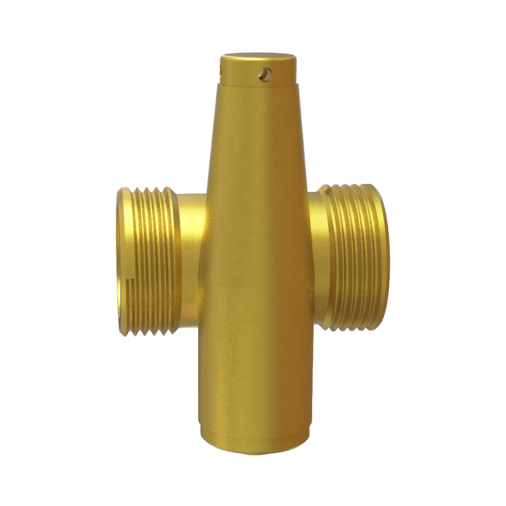
The Installation of the LF15-35-JQ Compact Heat Pump Freeze Protection Valve
1) It is recommended to install antifreeze valve connected with both pipes (flow and return) of outdoor heat ex changer of the heat pump(as shown in the fig E.
2) The antifreeze valve shall be installed vertically downward, to allow the drained water to flow out properly and free from obstructions.
3) The antifreeze valve shall be installed outdoor, at the position that can sense the lowest temperature of the system, and shall not be installed near the heat source which could interfere with proper function.
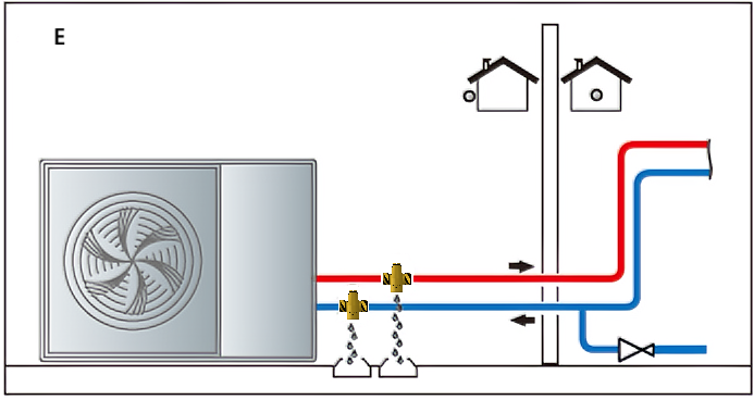
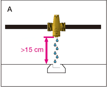
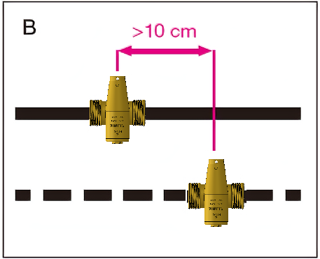
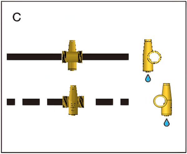
4) Leave at least 15 cm clearance from the ground (fig. A) to prevent the block of ice which may form below from stopping water from draining from the valve. Keep a distance of at least 10 cm between the antifreeze valves (fig. B), if the drains are facing the same way. For compact installation, devices can be installed on the same vertical axis; make sure the drains (fig. C)
5) Do not make any trap connections(fig D).
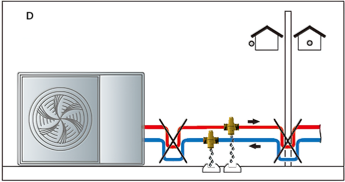
6) It is not recommended to connect the drainage pipe behind the antifreeze valve.This may cause the failure of antifreeze due to freeze blocking the drainage pipeline.
We are engaged in Freeze Protection Solutions for Solar Thermal & Heat Pump Systems over 20 years.
Trusted by heat pump manufacturers in Germany, Australia, and the USA.
MOQ: As low as 50 pcs for standard models (lower for samples)
Lead Time:
In-stock items: 1-2 weeks
Bulk production: 4-6 weeks (FOB China)
Shipping: We support FOB, EXW, and DDP to EU, US, AU, and SEA. DDP quotes available upon request.
Absolutely.
We support OEM and system integrators with:
– Standardized thread options: BSP (G1/2″, G3/4″) for EU/UK/AU, NPT (1/2″, 3/4″) for North America
– Customization options: port orientation, open/close temperature, or laser engraving
Just share your piping layout — our engineering team can assist with integration.
|
Comparison Criteria |
Freeze Protection Valve (Automatic Drain-Back Type) |
Antifreeze Fluid (Glycol-Based Closed Loop) |
|
Comparison Criteria |
Automatically drains water from collectors/pipes when temperature drops to 3-6°C, preventing freeze damage |
Circulates antifreeze fluid (e.g., glycol) in a sealed loop; heats domestic water via a heat exchanger |
|
System Compatibility |
Direct (open-loop) systems– ideal for retrofitting existing installations |
Indirect (closed-loop) systems–requires full system design from the start |
|
Initial Cost |
Low ($30–$80 per unit; simple installation) |
High ($500+ for heat exchanger, expansion tank, pump, glycol, and labor) |
|
Maintenance Cost |
Near zero (No consumables; purely mechanical) |
Moderate to high(Glycol replacement every 3-5 years; pH/concentration monitoring; leak checks) |
|
Environmental Impact |
Excellent No chemicals, only drains water; fully eco-friendly and compliant with green building standards |
Fair to poor Ethylene glycol: toxic, hazardous to soil/waterPropylene glycol: low-toxicity but still requires proper disposal |
|
Energy Consumption |
Zero(Gravity-driven drainage; no electricity needed) |
Required(Circulation pump runs continuously) |
|
Installation Complexity |
Simple(Retrofit possible in <1 hour; minimal plumbing changes) |
Complex(Full system redesign; best for new installations only) |
|
Climate Suitability |
Mild or occasional frost zones(e.g., inland Australia, Southern Europe, southern China) |
Severe cold climates(e.g., Northern Europe, Canada – long periods below -10°C |
|
Reliability |
High (no electronics; low failure rate) |
Moderate (depends on pump, sensors, and glycol condition) |
|
Typical Applications |
• Residential solar water heaters (direct type) • Outdoor piping in heat pumps • Emergency eyewash/showers in seasonal climates |
• New high-end solar thermal systems • Commercial heat pumps in cold regions |
|
Key Value Proposition |
Low-cost, maintenance-free, eco-friendly upgrade for existing systems |
All-weather reliability – best for new builds in harsh climates |